Losmandy Gemini GM8 |
|
|
Losmandy GM8 New Worm Block Development
Background
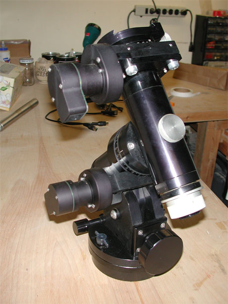
The GM8 is a fine German equatorial mount, solidly built and capable of carrying an 8” SCT without difficulty.
For visual observation, when fitted with the Gemini Goto system, it is likely one of the best value proposition in the
When it comes to CCD imaging, things begin to look different and one has to start worrying about the worm-gear mesh in order to ensure a smooth tracking.
Unfortunately, the mount, which is otherwise well designed, has a significant flaw when it comes to how the worm gear is held up: there are two holding blocks (also referred to as the wormblocks) fitted with ball bearings that are attached to a base plate.
The flaw lies in the fact that with this setup the worm has too many degrees of freedom when compared to the available number of hands of most mortals (2 as far as I know).
In order to adjust the worm-gear mesh properly, the worm needs to be pinched between the two blocks to minimize backlash. Then the assembly must be rotated to engage the worm into the main gear. Then, while the proper mesh has been reached, the blocks’ mounting bolts need to tightened, and this is where the third hand (or pair of hands) becomes needed.
In addition, this is typically done in the dark (and sometimes in the cold as well), in order to check via an eyepiece or ccd camera, how well the adjustment performs.
However, this can be dealt with after repeated trials and a good does of patience.
To make things a little more complex, the worm is linked to the RA motor via a coupler that should compensate for axial offsets. However, the RA motor is attached to the base plate via posts and the axis is not well aligned with that of the worm, leading to additional sources of not so smooth tracking. The mounting holes in the RA motor assembly have to be enlarged to effectively align both motor (gearbox output actually) and worm axes.
An additional problem comes up due to the design of the block. The bearing is 0/375” in diameter and this size leaves a very thin wall thickness for the block. Unless the wall is well machined, when it is clamped to the base plate, irregularities will interfere with the bearing outer race and ultimately with the rotation of the worm. Alas, the blocks are made of extruded aluminum and are not machined square or flat. This has led to the well known (in the Losmandy community at least) 76 second error (this number actually applies to the G11 mount, for the GM8 it is twice that amount since the GM8’s worm rotation period is 8 minutes or twice that of the G11 mount).
This error is not periodic and therefore cannot be corrected by traditional PEC (Periodic Error Correction). In many instances, it is not high enough that it cannot be dealt with by using an autoguider. However, there is an incentive to be able to achieve smooth tracking without autoguiding, when imaging with narrowband filters for example. Furthermore, one would prefer to have a well tuned mount period.
The GM8 presents more of a challenge than the G11 given its smaller main gear diameter and therefore greater periodic error (±22 arc-seconds typically from what my mount does and what others have reported online). The amplitude makes it more difficult (but not impossible) to perform long term exposures, even when autoguiding. This is of course highly dependent on the mount and how fiddling has or has not been done with it. There are many reports of GM8 users who have taken fairly good pictures without ever having to tweak anything.
Unfortunately, this is not my case, and this has led me to look for improving this situation.
Solutions
There have been (and still are) many discussions about solving this issue in the Losmandy User Group. The best one is likely the RS Wormblock, developed by Rainer Ehlert. Rainer devised a setup that has all pieces (worm, coupler and motor) referenced off a single aluminum block. In addition, he used thrust bearings and an axial adjustment to eliminate backlash. According to him and the one other amateur who duplicated his setup, the approach works as expected.
The plans are not available unfortunately, leading others to develop their own solutions.
The lack of an off the shelf upgrade kit got me thinking about my own solution.
The one thing I do not like about the RS Wormblock is that it does not address the thin block wall. On the other hand, I have a GM8 and it does not have to carry the same load as the G11. Therefore I figured that I could simply use 0.5” diameter bearings instead of the original 0.375” and not have to worry about radial stress too much.
Ideally, the best approach is a single block concept because it implicitly maintains axial registration between the two bearings. Alternatively, a two-part solution can also be viable provided a solid registration can be achieved
In the end, the second approach is what I settled on. After taking many measurements, I enlisted the help of a mechanical engineer at work to help me with the design and detailing of the concept
Description
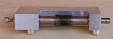
The new worm block is a two part unit with an axial adjustment. The parts were machined from the same aluminum block to ensure minimum misalignment. Registration is provided by two precision dowel pins, and the two pieces are fastened with 8-32 hex screws.
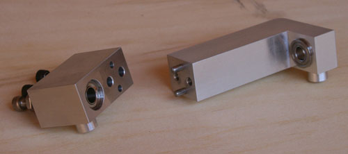
View of the two main pieces
The longer piece is also fitted with a flanged ball bearing (McMaster-Carr part number# 4262-T16). The flange provides the mechanical stop for the worm on the RA motor side.
The shorter piece contains a standard abec-7 0.5” ball bearing (McMaster-Carr part number# 3579-T37). It also has an adjustment piece driven by an 8-32 screw and locked by a nut that pushes on the outer race of the bearing to eliminate axial play.
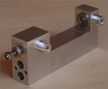
The wormblock assembled without worm gear
The unit keeps the same mounting tabs as the original blocks to maintain compatibility with the GM8 design.
The tab closest to the motor has the same diameter as the hole in the baseplate to limit the assembly to a circular motion only when engaging the main gear.
Assembly
Putting together the wormblock assembly is straightforward:
- Engage the worm into the flanged bearing
- Bring the matching piece over the worm and such that the dowel pins fit into their matching holes
- Fasten the two 8-32 screws. Done
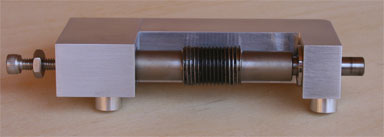
Wormblock Assembly prior to axial play adjustment
Axial play is removed by tightening the third screw until the worm cannot move laterally and still rotates freely. The locking nut is then tightened to prevent overdriving the screw later on.
Wormblock Assembly with axial play removed.
The unit can then be fitted onto the GM8 baseplate as shown below:
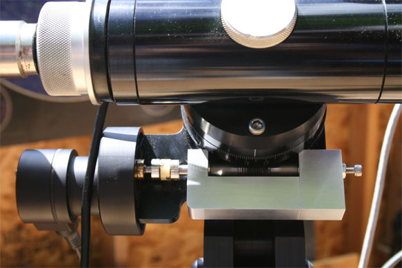
Wormblock Assembly Installed
Evaluation
You know what they say: Best laid plans…
So you can already guess that this was not an instant home run.
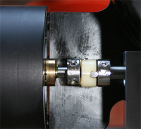
Before firing up Pempro, I looked at the fit and ran the system by hand and with the servo motor.
The good:
- It fits! Of course this was expected, yet it is based on measurements off the unit, not source drawings and it is after all a precision system.
- It adjusts! By simply rotating the right end (opposite the motor) to mesh the worm into the gear and rotating the axis, it is easy to tell when the binding point is reached. One can then use a free hand (the one rotating the axis) to tighten the screws into the mounting tabs. Voilà, job done.
- I can rotate the axis by hand (at the coupler level) without interference
- The motor/gear noise is very smooth and consistent, which is a major improvement.
The not so good:
- There is an offset between the gearbox and worm axes (see below):
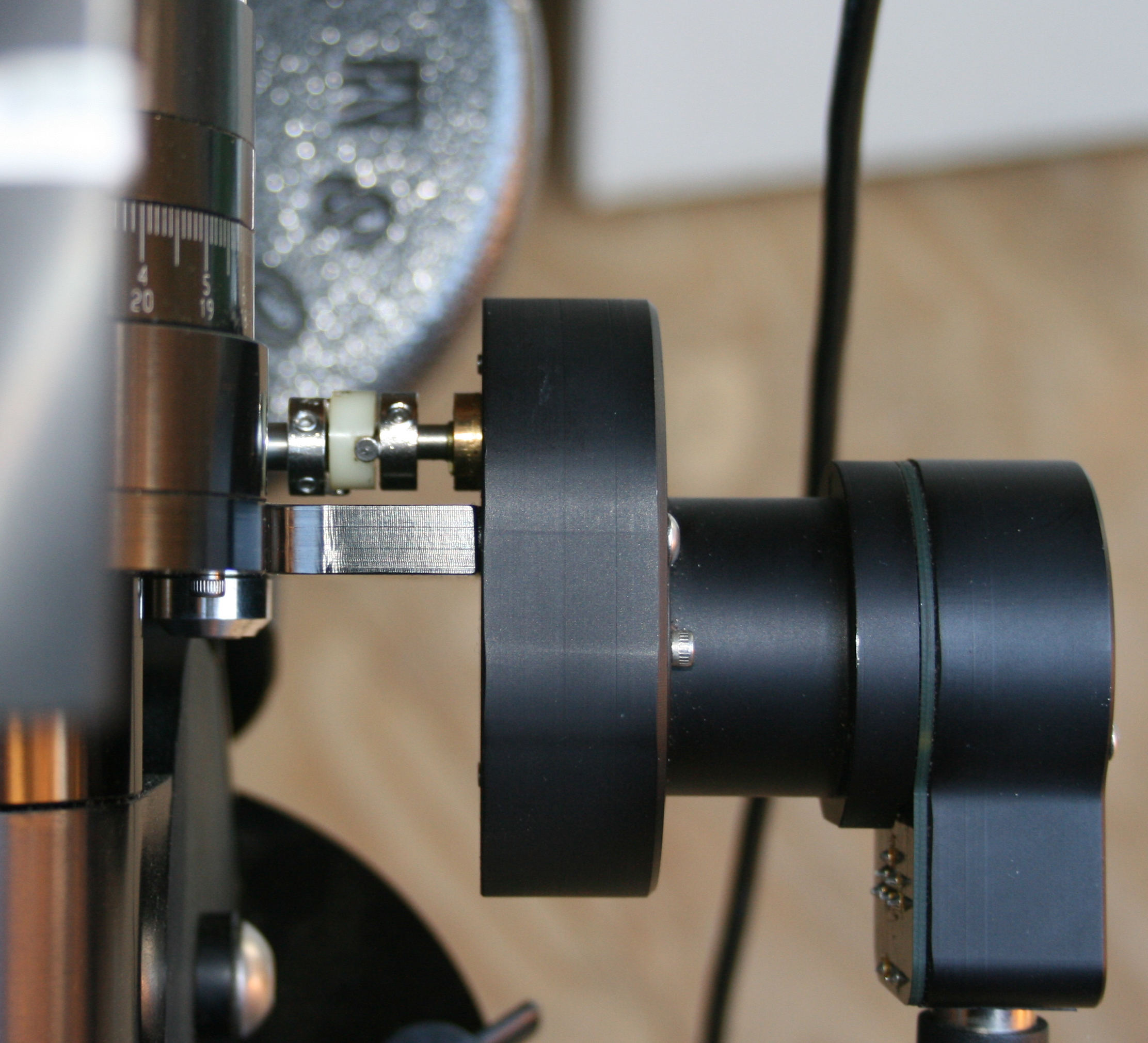
This had to be corrected and the solution consisted in enlarging the gearbox mounting holes to move the RA motor assembly down (and sideways as well)
Result below, a much better alignment:
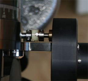
Post shaft alignment
PE Evaluation
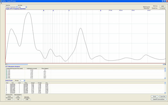
The first graph below shows an uncorrected periodic error report from PemPro with the original worm block holders. The 152 second errors shows very well (unfortunately) at about 3.5 arc-seconds
The second graph shows the same uncorrected periodic error report with the new wormblock. The 152-second error is still there, albeit reduced to 2.5 arc-seconds.
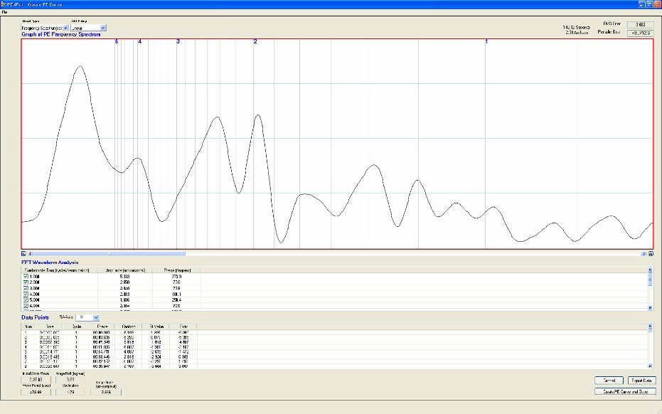
And there is the second peak at an odd-ball frequency that should not be there at all.
This was of course a bit disappointing. I also noticed several “RA Motor Lag” messages from Gemini during the PemPro scans, indicating something was not setup right.
After a few re-adjustments of both the axial play and the worm-gear mesh, things improved a little and led to the results below:
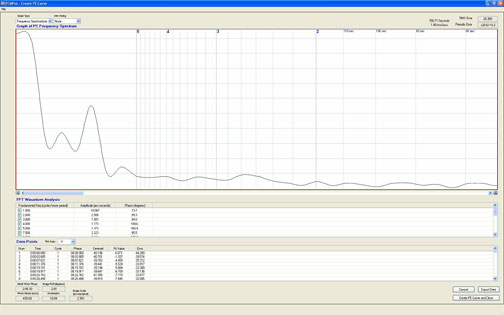
The ugly second peak is gone and the 152-second peak, while still present, has been reduced to less than 2 arc-seconds.
Using this as a basis for PEC, I ended up with a 7 arc-second peak to peak maximum error. While this may look good, the fact that the aperiodic 152-second error is still there makes this result irrelevant.
In conclusion, this design does not appear to be working well. Yet, the concept is sound. Therefore, something else is off.
I do not think it is due to irregularities of the bearings because the load is light (4” refractor) and the bearing housings have been precision machined.
The fact that I was still getting occasional “RA Motor Lag” errors indicates the worm is binding. But I had been fairly careful when adjusting the mesh to still be able to freely rotate the worm with two fingers holding the coupler.
The GM8 design is not easy to investigate because there is not much room to position mechanical reference, and it is also challenging to sneak in calipers.
Nonetheless, I retraced the many adjustments I had to do and hit upon the fact that I enlarged the gearbox mounting hole to lower the motor shaft. I did not have to do that with the original blocks. It could be that the new design lies too low with respect to the gear, which does not have a straight face.
My last modification was therefore to raise the wormblock above the baseplate using a metal shim. I used a 0.005” shim first.
This is where the system is at as of December 2007, and I now have to wait for my ccd camera to come back from upgrade in order to use PemPro and see if there is an improvement. I have not seen any “lag” message since I put this in back in late November but that does not necessarily prove much. I can take 5 and 10 minute guided exposures with round stars so life is still good. But I want to get this design worked out as I wish to put the C8 back on the mount and try to image smaller objects, at F/6.3.
Spring 2008 Update
So I finally got the ST8 upgrade and of course I immediately went about taking images using the internal guider. Well, no go. The darn thing would not calibrate: no matter what I did, I got the "insufficient move in X" message. In deference to SBIG support, Alan Holmes was very helpful and I finally figured out the problem was on my end and tied to the GM8 RA drive, once again. It took some time because I was able to calibrate with the external guider and PhD and this threw me off track.
It turned out to be the worm-gear mesh again: while guding worked ok until the end of November, it would not in January. The reason? Colder temperatures requiring adjusting the worm-gear mesh, and this is an iterative process in order to get it just right (not too loose and not too tight...).
On top of this, the weather was not playing nice in the East Coast and my work life was also consuming my energies, leaving little when it came to solving issues instead of being imaging. Finally, it started to click and I was able to get to 5 minutes and then 10 minutes guided exposures with the miniborg and DSI Pro imager using PHD. I still had trouble with the internal guide chip on the ST8: this thing is quite finicky!
The real improvements came in early April when I realized my polar alignment was just not good enough. Why did not I correct this earlier? Well, with only a few week ends and less than two hours on week night, I preferred to get images. Not the best approach, but more gratifying for a while. So in the end, I ran the Polar Axis Correction routine on the mount, and after two iterations I was within 3 arc minutes of the Pole. Not too bad and thanks to the Gemini alignment model capabilities, every object falls right in the center of the field of view. Very nice.
This resulted in better guiding. Of course, this is what everyone says on the net. I guess I should have started there but the absence of a finder on my scope and the cold made me more reluctant to spend the time outside to do this very necessary process. Lesson learned.
It was then time to use Pempro again and evaluate whether my contraption would pan out or not. I will save the reader any suspense: the contraption does help, PEC does not. The reason is that the wormblock design is not good enough to eliminate the a-periodic error and therefore using PEC only increases the number of corrections.
Below is a Pempro graph with PEC on. ± 5 arc-sec PED is pretty good for a GM8.
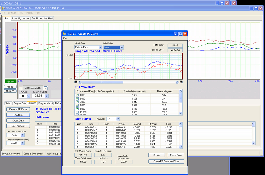
But it is not repeatable.
Below is the RA guide error log with PEC on then off, illustrating why in my case, PEC does not add value
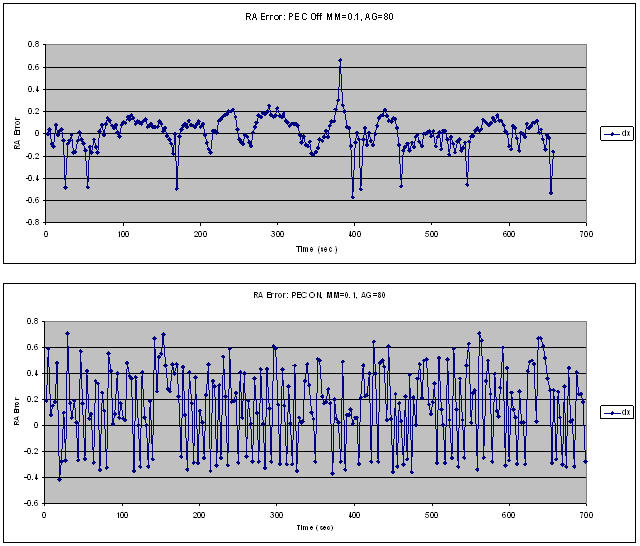
In both cases, the images were good with round stars, but clearly having PEC on does not look right.
Having said all that, the new wormblock is still a major benefit when it comes to adjust the mesh: loosen the screw, push in or out, tighten the screw and voila, job done. Compared to the independent blocks, it makes life much easier. I am leaving this on the mount and have no regret spending $450 to get to this. Others' mileage will vary and I have seen good images from stock mounts. I believe my mount, built in 1994, was not up to the general quality level of a typical Losmandy from this standpoint.
In order to get quality images with the C8 on, the design needs to be improved and adding thrust bearings while tying the motor mounting to the wormblock is the right way to go.
As of 04-30-08, I will be the owner of a G11, bought off Astromart, and my GM8 efforts will likely end. All pictures on the site up to this date were taken with the GM8 and they are a testimony to what can be done with this nice mount.